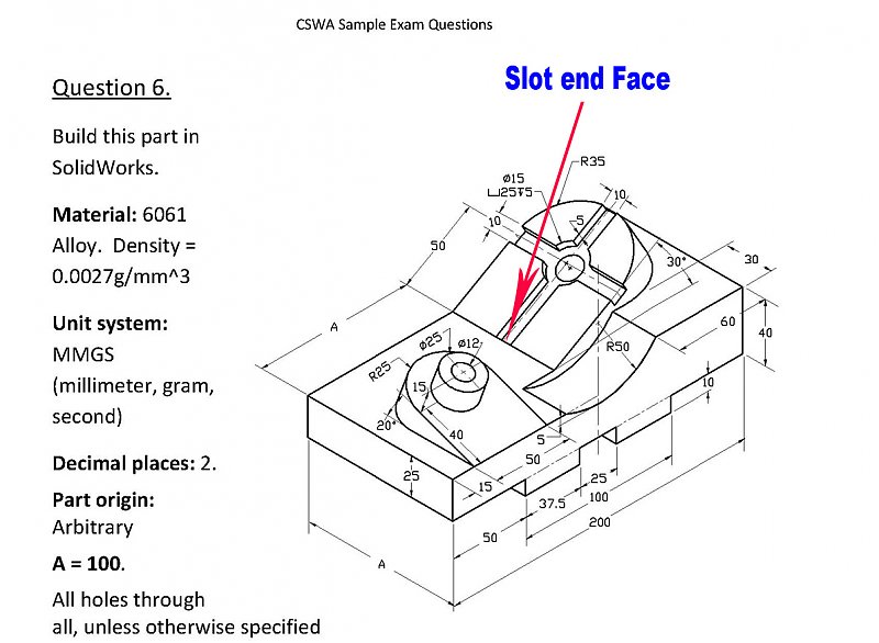
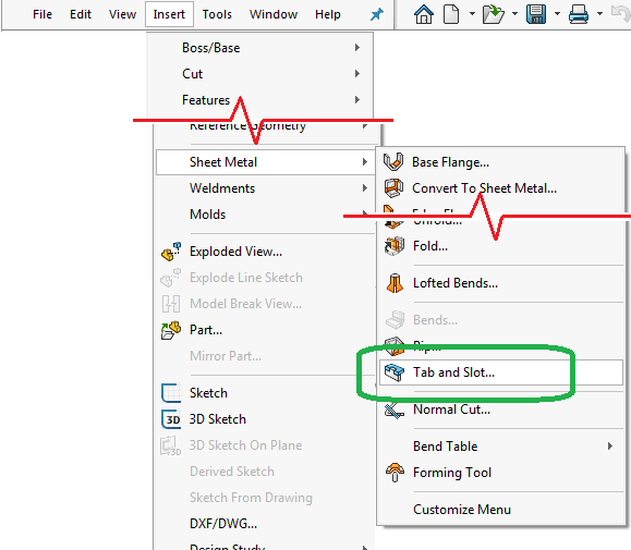
Ever since the additions of the slot sketch tool for 2009 and the Hole Wizard Slot for 2014, SOLIDWORKS almost seems like a whole new software for the those who design machined parts. Adding these tools were long overdue. Additionally, SOLIDWORKS supports the standard methods for dimensioning slots when they are created by using these tools. See more at: about the Tab and Slot SheetMetal Feature in SOLIDWORKS 2018 with sheetmetal multi-bodied pa. Every year, SOLIDWORKS makes several enhancements to its software. In particular, they have made creating complex sheet metal parts even easier. Today we are going to look at creating a slot in a sheet metal cylinder. As you would expect, there are several ways to accomplish this in SOLIDWORKS.
I need the dimensions marked from center to center without holes like i done in the file which is attached
2 Answers
You can construct a vertical 'centerline' on each of the rectangles and place the dimension on the centerlines.
To construct the centerlines, click insert>annotation>centerline, and select the 2 vertical edges of each rectangle.
You can delete the holes before or after, but before would probably be easiest and ensure the dimension didn't accidentally reference the holes.
As mention by robert hoyt You can use centerlines.
Alternatively you can select smart dimenion tool and then right click on both horizontal lines and select 'Select Midpoint' option. It will give similar results.
Do you know how to do slot sketching in SolidWorks graphics area? The slot tool contains mainly two types and are straight and arc slots. In the 7th part of SolidWorks Tutorial, you are going see how to straight and arc slots, which are explained with aid of images and also explains the slot property manager in detail.
Table of Contents
Note: You can control the dimension of the arc by using “Slot Property manager” or using “Smart Dimension Tool”
SolidWorks Tutorials 6: How to Use Slot Sketching Tools

The straight slots and arc slots are main two type’s slot sketching tool inside the SoildWorks Sketch. Like, different rectangle/arc drawing methods, slot sketching tools contains 3 point and centerpoint drawing methods. Let see each one of them in detail.
Note: This is just tutorial showing how to use slot tool, not showing any product drawing or designing in it. If you are advanced SolidWorks user please avoid it. This Solidworks tutorial is for beginners, students or people likes to learn about SolidWorks.

Checkout Best SolidWorks Training Materials here.
SolidWorks Tutorials 6: How to Draw Straight Slot

Using the “Straight Slots” tool, you can draw linear slots on the sketch entity. Two of the drawing methods are Straight slots and Centerpoint slots. These slots have additional option in property manager menu like center to center and overall length setting.
Step 1
Open the Solidworks and New part File. If you don’t know it, Read How to Create New Part File. Select the Plane (e.g. Top Plane) and normalize using the “Normal To” Button.
Step 2
You can access the “Straight Slots Tool” button from the command manager and Menubar. Click on the Straight slot button to select it which is shown in the above figure.
Step 3
To draw the straight slot you have to select 3 points.
Drag the mouse pointer to sketch area and click the mouse left button to set the “Point 1” which is shown in the above figure.
Drag the pointer to left side (in figure) to set the “point 2”.
Again drag it to set the “point 3” and that way you can complete the Straight slot drawing.
Related SolidWorks Sketch Tools Tutorials:-
Additional Info: Slot Sketching Property Manager
Solidworks Drawing Slot Machine
The property manager of slots sketching tools helps to adjust the dimensional and their positions in the X-Y axis or plane. Let us see the each components of the property manager menu.
Curved Slot Solidworks
Slot Type: In this section, you can select any rectangle type such as straight, centerpoint straight, 3 point arc and centerpoint arc slot.
Existing Relations: If you select the each portion of the slot by using “select” tool, you can see the existing relations.
Solidworks Slot Callout
Parameters: here you set the dimension of your slot dimensions and position on the plane you selected.